RP2350A Development Board
New Product Launch
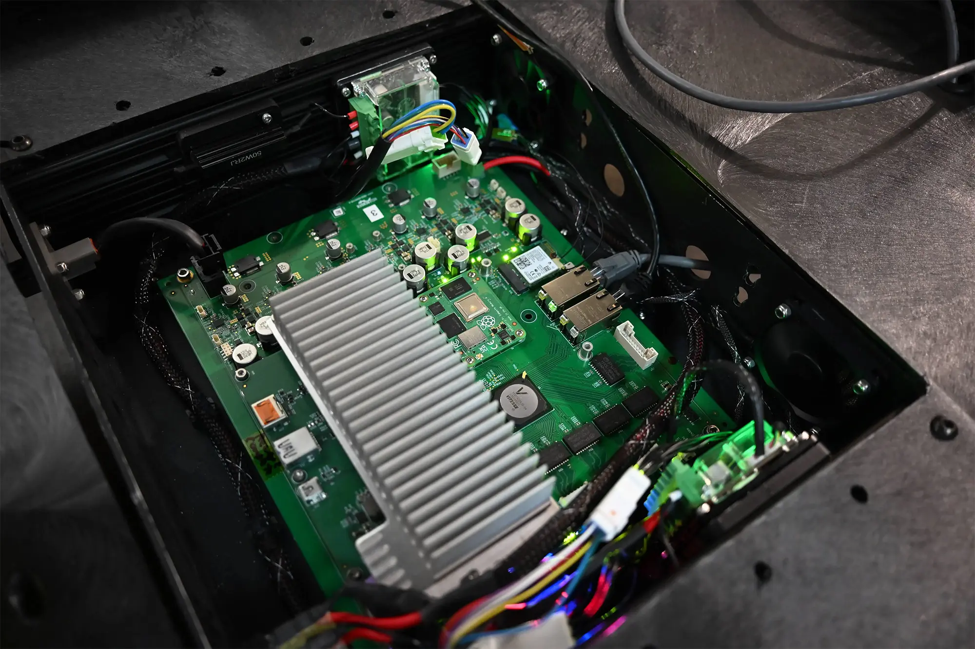
The Hellbender Raspberry Pi RP2350 development board is designed to be a general purpose microcontroller and sensor board ready to be integrated into any project.
Key features include flat back, 46-pin castellated IO headers, USB type C, SWD, µSD card, LiPo battery power and charging, integrated RTC, IMU, Temperature, Pressure, Relative Humidity, and QWIIC connector support. This board is supported through the Raspberry Pi PICO SDK .
This board is produced onsite at our Pittsburgh, PA facility.


Store Now Open
Need a custom
AI-Vision System?
Specifications
| PCB Interface | 2x 23pin castellated edge connectors |
| Power | USB-C 5V |
| Battery | 2S to 4S (jumper select), 10k NTC thermistor support |
| USB | 1x USB 2.0 debug port via USB-C connector |
| Debug / Serial | 2 I2C channels accessible via QWIIC connector 3-pin JST SWD debug connector |
| Radio | 3x Standoffs around 12pin JST (0533071271) for expansion LoRa module 3V3, GND, SPI, 4x GPIOs |
| Miscellaneous | 128Mbit flash memory 2x tri-color LEDs addressable by I2C RTC 6-axis IMU (3-axis accelerometer, 3 axis gyroscope), 20,000g shock tolerant Temperature, Pressure, & Relative Humidity SD card slot U.FL connector to the crystal oscillator |
| Environment | Recommended operating temperature -20 to 80° C |
Block Diagram


Pin Map Table
| Line | RP2350A Pin | Fn | PICO SDK Default Fn for that GPIO | Hb RP2350 Dev Board Pin | Hb Silk Screen | Hb Net Name |
|---|---|---|---|---|---|---|
| 1 | 13 GPIO9 | J3-1 | 9 | SPI CD CS | ||
| 2 | 09 GPIO6 | J3-2 | 6 | SPI SCLK | ||
| 3 | 10 GPIO7 | J3-3 | 7 | SPI MOSI | ||
| 4 | 14 GPIO10 | J3-4 | 10 | LORA IO1 | ||
| 5 | 15 GPIO11 | J3-5 | 11 | LORA IO3 | ||
| 6 | 03 GPIO1 | J3-6 | 1 | IMU INT1 | ||
| 7 | 12 GPIO8 | J3-7 | 8 | BAT INT | ||
| 8 | J3-8 | GND | GND | |||
| 9 | 08 GPIO5 | I2C0 SCL0 | J3-9 | 5 | SCL0 | |
| 10 | 07 GPIO4 | I2C0 SDA0 | J3-10 | 4 | SDA0 | |
| 11 | 05 GPIO3 | I2C SCL1 | J3-11 | 3 | SCL1 | |
| 12 | 05 GPIO2 | I2C SDA1 | J3-12 | 2 | SDA1 | |
| 13 | 02 GPIO0 | J3-13 | 0 | XIP CS1n | ||
| 14 | 56 QSPI CLK | J3-14 | SCLK | QSPI SCLK | ||
| 15 | 55 QSPI SD3 | J3-15 | SD3 | QSPI SD3 | ||
| 16 | 58 QSPI SD2 | J3-16 | SD2 | QSPI SD2 | ||
| 17 | 59 QSPI SD1 | J3-17 | SD1 | QSPI SD1 | ||
| 18 | 57 QSPI SD0 | J3-18 | SD0 | QSPI SD0 | ||
| 19 | NA | J3-19 | SNK | FUSB SNK | ||
| 20 | NA | J3-20 | SRC | FUSB SRC | ||
| 21 | NA | J3-21 | GND | GND | ||
| 22 | NA | J3-22 | 3V3 | 3V3 | ||
| 23 | NA | J3-23 | VBAT+ | VBAT+ | ||
| 24 | NA | J4-1 | VBUS | VBUS | ||
| 25 | NA | J4-2 | VSYS | VSYS | ||
| 26 | NA | J4-3 | 3V3 | 3V3 | ||
| 27 | NA | J4-4 | GND | GND | ||
| 28 | NA | J4-5 | ORNT | FUSB ORIENT | ||
| 29 | 37 GPIO25 | J4-6 | 29 | USB INT | ||
| 30 | 40 GPIO26 / ADC0 | J4-7 | 26 | ADC0 | ||
| 31 | 41 GPIO27 / ADC1 | J4-8 | 27 | ADC1 | ||
| 32 | 43 GPIO29 / ADC3 | J4-9 | 252 | LORA nREST | ||
| 33 | 36 GPIO24 | J4-10 | 24 | LORA BUSY | ||
| 34 | 33 GPIO21 | J4-11 | 222 | SPI LORA CS | ||
| 35 | 32 GPIO20 | J4-12 | 232 | SPI MISO | ||
| 36 | 35 GPIO23 | J4-13 | 212 | CLK GPOUT1 | ||
| 37 | 34 GPIO22 | J4-14 | 202 | CLK GPIN1 | ||
| 38 | 31 GPIO19 | SPI0 TX / MOSI | J4-15 | 19 | HSTX8 | |
| 39 | 29 GPIO18 | SPI0 SCLK | J4-16 | 18 | HSTX7 | |
| 40 | 28 GPIO17 | SPI0 CS | J4-17 | 17 | HSTX6 | |
| 41 | 27 GPIO16 | SPI0 RX / MISO | J4-18 | 16 | HSTX5 | |
| 42 | 19 GPIO15 | J4-19 | 15 | HSTX4 | ||
| 43 | 18 GPIO14 | J4-20 | 14 | HSTX3 | ||
| 44 | 17 GPIO13 | J4-21 | 13 | HSTX2 | ||
| 45 | 16 GPIO12 | J4-22 | 12 | HSTX1 | ||
| 46 | 42 GPIO28 / ADC2 | J4-23 | 28 | ADC2 |
Dimensional Drawing


Operation Notes
WARNINGS
- This product should only be connected to an external power supply rated for USB-C.
- The RTC has no on-board battery backup, if backup is desired an external battery must be added.
- This product should be operated in a well-ventilated environment, and if used inside a case, the case should have appropriate cooling capabilities or else not be sealed.
- This product should be placed on a non-conductive surface in use and should not be contacted by conductive items.
- The connection of incompatible devices to the various connectors may affect compliance and result in damage to the unit and invalidate the warranty.
- All peripherals used with this product should comply with relevant standards for the country of use and be marked accordingly to ensure that safety and performance requirements are met.
SAFETY INSTRUCTIONS
To avoid malfunction or damage to this product please observe the following:
- Do not expose to water, moisture, or place on a conductive surface while in operation.
- Avoid mechanical or electrical damage to the printed circuit board and connectors.
- Avoid handling the printed circuit board while powered and only handle the edges to minimize the risk of ESD.


